


CircuitLogix Pro is an electronic design automation (EDA) software tool from Logic Design Inc. that seamlessly integrates schematic capture and simulation in one complete program. Professional schematic capabilities include a built-in device editor, a macro feature for hierarchical devices, and automatic wire routing. These features allow users to quickly create high-quality schematics for documentation. CircuitLogix Pro features a 2D simulator as well as a 3D simulator called 3DLab.
CircuitLogix Pro allows users to simulate any combination of analog and digital components. Mixed-model simulation is as easy and the speed and accuracy rivals EDA tools costing thousands of dollars. Along with the expanded simulation capability, the professional version features a larger device library of over 10,000 devices, easier SPICE model import, and no limit on the number of pins for an individual device.
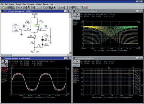
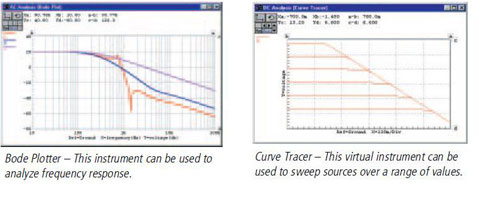
With the pro version, designers can export CircuitLogix schematics as PCB netlists for use in printed circuit board layout products. CircuitLogix features a proven, accurate 32-bit SPICE3f5/XSpice-based simulator for analog and mixed-signal circuits, and a fully interactive digital logic mode when only logic simulation is needed. The simulations give real-world results designers can trust. The professional version of CircuitLogix allows designers to test and trouble-shoot circuits in a "virtual electronics lab", without worrying about bad parts or faulty connections that often plague traditional prototyping. And with a click of the free-floating Probe tool, users can instantly see waveforms and measurements on virtual instruments like the digital oscilloscope, curve tracer, bode plotter or digital multimeter.
Seamlessly integrated with CircuitLogix Pro’s schematic capture is the ability to quickly simulate and analyze your design within the same workspace. And you don’t have to generate netlists, or pre-define test points or probes to run the simulation – just click the Run button! CircuitLogix electronics circuit simulation uses a proven, accurate SPICE-based simulator that produces real results you can trust. Propagation delays, setup and hold times, and power supply-dependent output levels of each digital part are modeled accurately to simulate the real-world specifications. CircuitLogix Pro incorporates the latest SPICE and XSPICE tools to provide "true" mixed analog/digital simulation, meaning you can simulate any combination of analog and digital components without inserting D/A or A/D converters.
One of the biggest advantages that sets CircuitLogix apart from the competition is the ease of taking measurements. Simply point and click with the context-sensitive Probe tool during simulation, and results are immediately displayed on the selected instrument .
Click on multiple points in the circuit to view any number of waveforms simultaneously. Best of all, you don’t have to manually wire in scopes or specify your test points beforehand. This is by far the most efficient program for quickly analyzing your circuit’s performance.
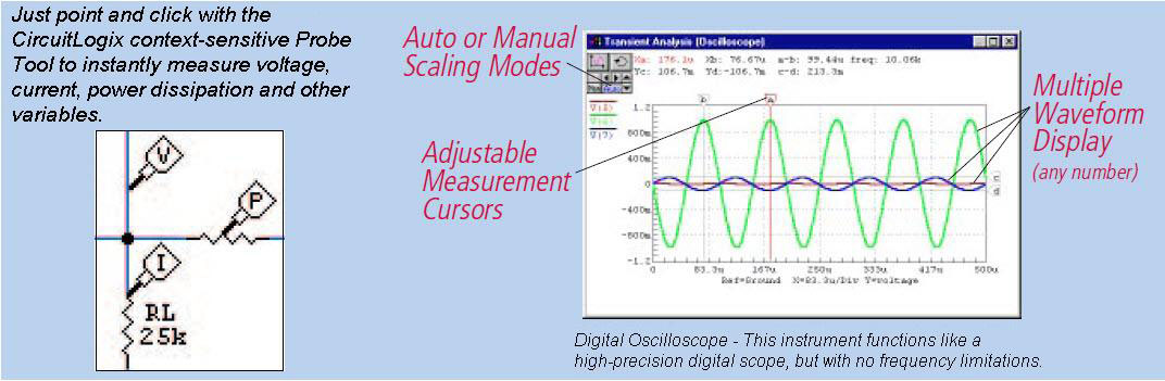
CircuitLogix Pro comes with an array of virtual instruments, allowing you to quickly plot data from any points in your circuit. These instruments provide advanced capabilities including multiple trace display and the ability to store and recall waveforms.
CircuitLogix gives you as much control over the simulation parameters as you want. You can adjust all the SPICE options, including aspects like time step, iteration limits and the method of integration. You can also decide whether data is collected for the entire circuit or just specific nodes. But for those who don’t need access tothe more technical aspects, CircuitLogix handles everything and won’t force you through complex SPICE commands or difficult syntax.
Creating high-quality schematics in CircuitLogix Pro is as easy as selecting parts and placing them on the workspace. Navigate through CircuitLogix’s thousands of parts and models with the graphical device HotKey shortcuts to place them with a single keystroke.

Simply click on a device pin or wire with the Wire tool, drag and release onto another device pin or wire and CircuitLogix instantly routes the wire for you. The AutoWire feature highlights exactly where the connection will be made before you release, ensuring perfect wiring every time. You are also free to place wires manually anywhere in the workspace. Unlike other schematic programs, CircuitLogix gives you full control of wire placement. For added convenience, wires will automatically "rubberband" when you move a device, and wires can be cut, extended or repositioned at any time.

CircuitLogix also supports bus wires and "dashed-line" wires. Bus wires contain multiple individual wires, and each bus wire is numbered, as is each individual wire in the bus. Using bus wires helps keep schematics clean and uncluttered. "Dashed-line" wires are ideal for highlighting logical blocks or sections of a schematic for documentation. CircuitLogix gives you complete visual control of your circuit. Use the printout borders, customizable title box and enhanced pin annotation options to create quality schematics for documentation, design review, presentations or record keeping.
The Symbol Editor featured in CircuitLogix Pro gives you the flexibility to create custom symbols and add them to the library. There are no pin limitations, so you can create symbols for microprocessors and other complex devices. Base your new symbol on an existing one, or create one from scratch using a variety of drawing primitives. Using a new or existing symbol, you can then create custom simulatable devices. You can alter the parameters of an existing device and save it as a new one, or use the Macro feature to create the internal circuitry of a new device and add it to the library. CircuitLogix also imports SPICE models directly (these can usually be obtained from manufacturers) to create new working devices.

With CircuitLogix Pro, you simply doubleclick on a device to edit a wide variety of parameters. You can select models, or edit device values, designation and label information, SPICE data and many other aspects of the device. Because CircuitLogix uses vector-based graphics, printed schematics come out clean and sharp at any size. You can also Copy and Paste schematics and waveforms into other programs
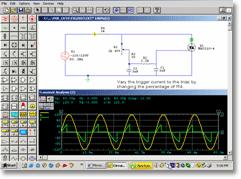
Using simulation tools like CircuitLogix, students, engineers, designers, and bench technicians all have the freedom to try all the "what-if" scenarios - changing parts or component values, then re-running the simulation to see how changes affect the circuit's operation and performance. This type of testing is not always feasible with traditional breadboarding methods.
We have made the support of education a strong company focus, and as such we have in place a generous educational discount policy which offers affordable individual and site licenses on all products, for education institutional labs and classrooms. These site licenses allow you to install the software on multiple computers, or on a network enabling multiple users at the same time. And best of all, if you decide later to increase the size of your license, we'll give you full credit for what you've already purchased towards the new larger license! Please contact the sales department at Logic Design for educational discounts and multi-user site license pricing.
The pro version of CircuitLogix allows you to design and edit your own devices and models for an unlimited number of virtual components. It also includes 3DLab, which is a revolutionary software product that combines an interactive 3-dimensional learning environment and "real world" electronic devices and tools to greatly enhance the user's comprehension of electronics. It includes:
The features of CircuitLogix Pro include:
- Highly intuitive graphic user interface
- Versatile circuit node naming
- Automatic point-to-point wiring
- Wire connectivity maintained during moves
- Automatic Bill of Materials generation
- PCB netlist export
- Snap grid with device "nudging" using arrow keys
- Device rotation in 90 degree increments
- Rotate, Mirror and Repeat placement
- Undo, Redo, Duplicate and Merge circuits
- Zoom in or out 10%-1000%
- Wide range of user-definable colors
- Fully stylized multi-line text
- Alphanumeric pin designations; barred pins; vertical or horizontal pin orientation
- Fit-circuit-to-window feature
- Click-and-drag wire repositioning
- User-sizable connection area for wires
- Multiple wires to the same device pin
- Cut and extend wires
- Context-sensitive on-line Help
- Right-click pop up menus for quick access to editing tools and features
Extensive component library includes:
Semiconductors: Semiconductor Resistors & Capacitors, Diodes, Schottky & Zener Diodes, Bridge Rectifiers, Varactor
Displays, Indicators, Switches: LEDs, 7-Segment LEDs, Hex Display, Hex Key, Logic Display, NC PushButton, NO PushButton, SPDT PB, Piezo Buzzer, Pulser, Latch Coil, Polar Latch, Rocket, SCOPE, Stepper, Stoplight, Window
Digital primitives: Gates, DeMorgan symboled gates, buffers, inverters, flip-flops
Digital ICs: 1K RAM, 32x8 PROM, complete selection of 40xx, 41xx, 45xx, 47xx, 74xxx IC's
Linear ICs: Op Amps, Comparators, Timers, Buffers, CDAs, Modulators, A/D & D/A converters, PLL, VCO
Transistors, FETs: BJT's, IGBTs, UJTs, PUTs, MESFETs, MOSFETs, Darlingtons
Relays: SPST, DPDT, Individual contacts and coils (enable creation of any relay)
Supplies, Sources: Battery, Voltage Terminal, Signal Generator, I Source, V Source, I->I Source, V->I Source, I->Switch,V->Switch, I->V Source, V->V Source
Math devices: A wide variety of devices for manipulating quantities
Miscellaneous Devices: Crystals, Fuses, Transformers, DC Motor, F-V & V-F converters
Transmission lines: Lossles, Lossy, and Uniform Distributed RC
Vacuum Tubes: 12AU7, 12AX7, 5879, 6L6GC, 6SN7, 7199P, 7199T
Instruments: Oscilloscope, Digital Multimeter, Bode Plotter, Curve Tracer, Data Sequencer, Signal Generator, Logic Analyzer, Logic Probe, Logic Pulser
Simulation Controls: Initial Condition and Nodeset devices
Miscellaneous: Optoisolators, Photodiodes, Regulators, References, SCRs, Triacs
Every copy of CircuitLogix Pro includes a comprehensive printed User Manual and Device Library Guide.